
Planar Structures: Very Large Scale Prototyping
Lawrence Sass Massachusetts Institute of Technology Lujie Chen Singapore University of Technology and Design
Introduction
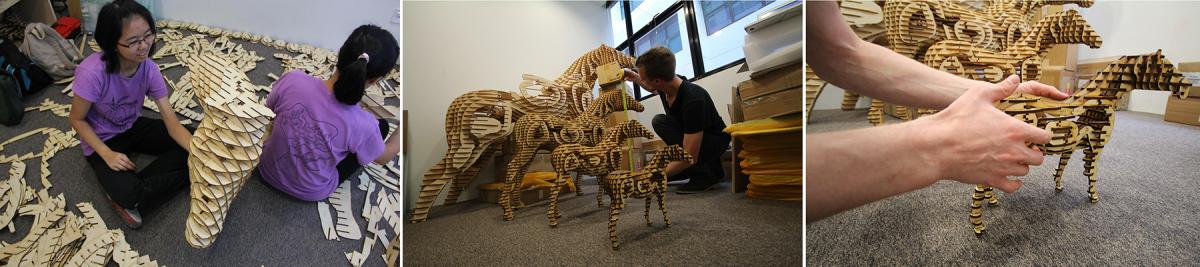
Very Large Scale Prototyping (VLSP) is systems exploration leading to an instrument (software) for physical production of artifacts many length scales greater than the manufacturing device. Novelty will come from an intelligent interface that will support options for user input into model construction. User input is needed to change material formation in order to simplifying assembly tasks and or elevate the quality of the finished model. In VLSP model production starts by generation of planar components as 2D drawings for laser cutting from a 3D model. After fabrication by laser cutter or CNC machining and manual assembly with snap together features embedded within each component (Figure 1a). Once finished the user can evaluate models by hand and eye leading to new model generation with some variables in size. Best is larger models can be refabricated from the same 3D models (Figure 1b). Current studies explore model generation as an emerging process, meaning model formation of planes need to change with size. We hypothesis that in most cases the user cannot predict model outcomes. Model outcomes are discovered only during assembly and post assembly applications (Figure 1c). We seek to characterize possible changes in model configuration based on user feed back.
Problem Statement
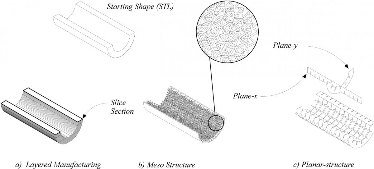
Planar structures are within an area of research defined as Additive Manufacturing (AM) whose principle system is centered on the production of horizontal slices through an initial 3D model [1] [2] [3]. Slicing systems start with meshed data followed by a system of contour optimization in order to smooth or fill regional areas within the section (Figure 2a). Advanced systems work with different line types such as contours composed of NURB lines as a way to generate very smooth edges however all systems are limited in physical output size [4] [5]. There have been attempts to fabricate large-scale by way of additive manufacturing [6] [7] [8] [9] and a recent attempt to print large was found in foam cutting of large structure [10]. Unfortunately additive models are limited in ways to control performance such as structural loading, assembly tolerance between parts with features, hardness and most important they are limited in variation by machine size. Alternatively, potential success in performance and size can come from techniques found in cellular based prototyping as ways to measure and design for performance [11]. A Mesostructure is organization of struts and rods similar to truss formation fabricated into a shape with varying results (Figure 2b) [12] [13] [14] [15]. Unfortunately, although proposed, there is little evidence of the potential to fabricate large objects built from a collection of Mesostructures [12]. Last, opportunities to fabricate large are evident by way of planar structures; a composition of interlocking planes elements. Planar structures are built of interlocking planes along two axes. The system is also referred to as waffle structures in some fields such as architecture [16] [17] [18]. We believe there are many opportunities for discovery and development of a scalable rapid prototyping system for manufacturing of large desktop models and finished products (Figure 2c).
Research Approach and Methods
The primary objective or VLSP has been to address issues related to design scaling when considering physical production from 3D printing devices. Creation of a planar structure starts with a 3D model that is contoured across two axes. This method of data extraction was originally explored at MIT as a way of building architectural surface models [19]. This method stands in contrast to the commonly accepted single axis system found in layered manufacturing (rapid prototyping). A variety of researchers have also used this method (biaxial contouring) for design and tool path generation of toys, furniture, and architectural models manufactured with laser cutters [16] [19].
The VLSP process is presented below. It demonstrates model generation of contours from the original shape (STL) along two axes and steps used to add features before concluding as 2D drawings and a 3D model of components (Figure 3). Once fabricated the goal of the vertical contours is to physically support horizontal contours as a way to maximize material and increase model size as a 3D shape. The system is designed to add features such as slots and interlocking shapes into the finished horizontal and vertical components. A major challenge was found when calculating and programming functions to split contours into multiple segments (tiling) in support of scaling. Although systematic splitting of vectors was challenging the level of complexity grew from a need to control interference between features such as slots and assemblies and splits between contours. The result is a principle of geometric ordering we call segment lapping that is use control model performance, maximize material use, extend past machine limitations and measure human factors in physical assembly.
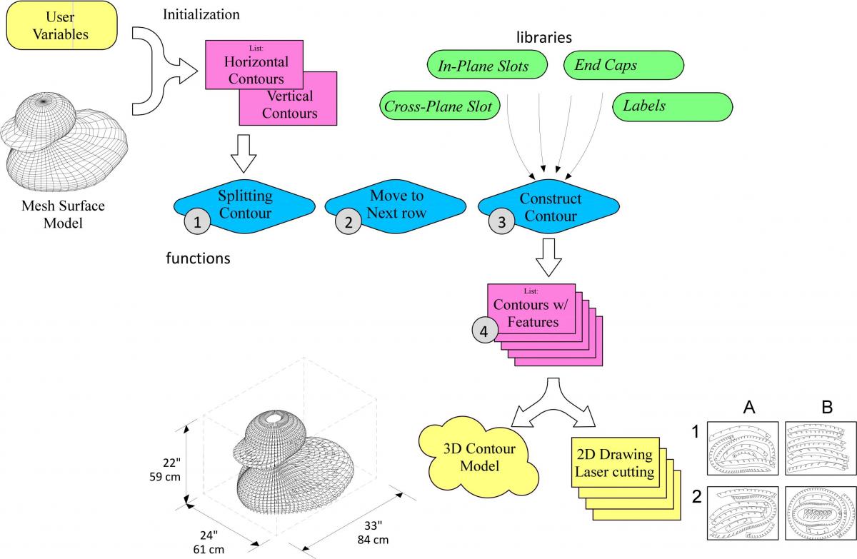 Figure 3. A generative process from starting STL model to finished 3D model and 2D drawings
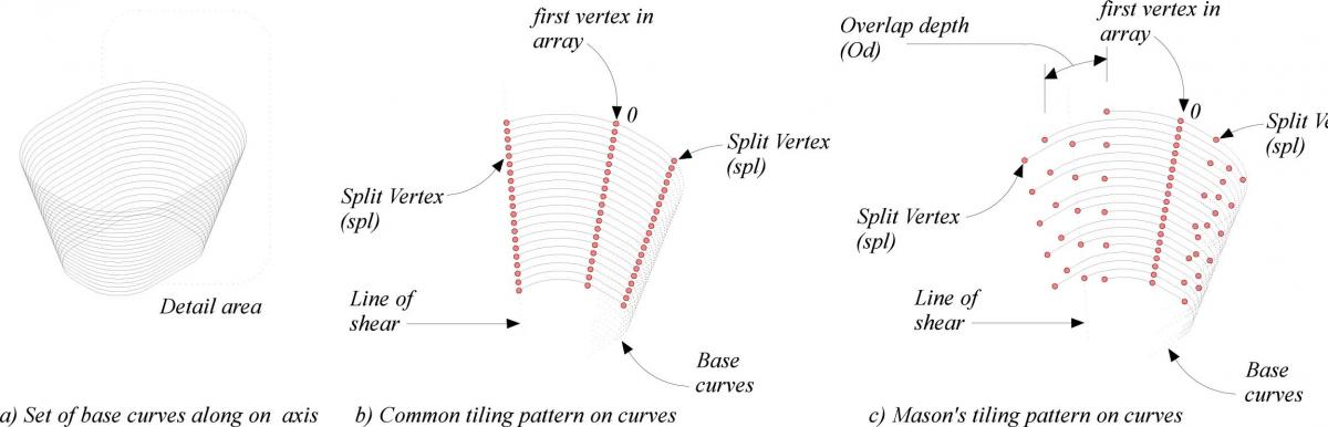
The system generates component by splitting the initial contours into segments limited to machine size. The result is an organized system of segment lapping as a way of elevating model quality controlled by three variables (Figure 4).
- Cross Overlapping Depth (Od). Composed of long interlocking segment where strength is measured by the depth of each segment
- Split Vertex (spl). Breaks or splits in segment leading to contour split at different points through out the model.
Results
We challenged the system by fabricating three models at MIT (See Page One: Duck, Bust & Merlion) each from thin wood sheets. All final models were greater than one-meter square assembled manually without glue or mechanical fasteners. Challenges in this study ranged from best methods to generate contouring geometry from mesh surface models to methods to build algorithms of carpentry techniques (lapping). We have also applied this technique to build very large abstractions of animals from CAD models (Figures 5). In this figure we show a large and small triceratops manufactured in layers of cardboard. The exact same model was used to generate machine data for the small and large dinosaur. The larger dinosaur was constructed of 1049 layers, the smaller dinosaur of 196 layers. The horse is generated of contours in two directions opposed to one direction in the dinosaurs.
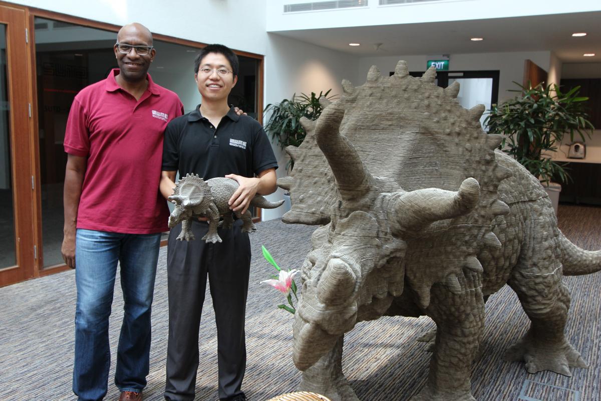 Figure 5 Triceratops large and small constructed of layers from the same mesh model. The horse model, although of a varied description was also constructed from the same software of fewer layers.
Impact of Large Scale Prototyping
We strive to build an interactive system for prototyping where the designer can change production variables. We expect that long term this system can affect many design industries in particular watercraft, civil engineering and building construction.
- Economic desktop prototyping of big products: The results affect the economy of production through efficient production of large artifacts using low cost materials.
- Efficient scaling from small to big: Data generated for desktop models is the same as data generated for full-scale manufactured goods. Previous examples of efficient scaling demonstrated that geometry used to manufacture desktop models embodied the same constraints as models built at larger scales of the same geometry (however thicker material).
- Rapid Rescue Delivery: Planar structures scale from small desktop products of larger products. It could possible to design and fabricate rescue products for disasters, houses, kitchens, hospitals, windmills for power and temporary morgues and worship structures.
References
- Jacobs, F (1992) Rapid Prototyping & Manufacturing: Fundamentals of Stereolithography Dearborn, MI : Society of Manufacturing Engineers, Dearborn MI.
- Cooper, K (2001) Rapid Prototyping Technology: Selection and Application Marcel Decker, New York.
- Dolenc, A and Makela, I. (1996) An accurate slicing procedures for layered manufacturing techniques, Computer-Aided Design, 28(9), 683-697
- Kulkarni, Prashant, Anne Marsan, and Debasish Dutta. "A review of process planning techniques in layered manufacturing." Rapid Prototyping Journal 6.1 (2000): 18-35
- Tata, Kamesh, et al. "Efficient slicing for layered manufacturing." Rapid Prototyping Journal 4.4 (1998): 151-167.
- Thomas, C. L., Gaffney, T. M., Kaza, S., & Lee, C. H. (1996) Rapid prototyping of large-scale aerospace structures, In Aerospace Applications Conference, 1996, Proceedings, 1 (4), 219-23
- Khoshnevis, B (2004) Automated construction by contour crafting-related robotics and information technologies Automation and Construction, 13 (1), pp. 1-19.
- Brooks, H., & Aitchison, D. (2010). A review of state-of-the-art large-sized foam cutting rapid prototyping and manufacturing technologies. Rapid Prototyping Journal, 16(5), 318-327.
- Horváth, I., Vergeest, J. S., Broek, J. J., Rusak, Z., & de Smit, B. (1998). Tool profile and tool path calculation for free-form thick-layered fabrication. Computer-aided design, 30(14), 1097-1110.
- Brooks, H., & Aitchison, D. (2010). A review of state-of-the-art large-sized foam cutting rapid prototyping and manufacturing technologies. Rapid Prototyping Journal, 16(5), 318-327.
- Rosen, D. W. (2007). Computer-aided design for additive manufacturing of cellular structures. Computer-Aided Design and Applications, 4(5), 585-594
- Wang, H., Chen, Y., & Rosen, D. W. (2005, January). A hybrid geometric modeling method for large scale conformal cellular structures. In ASME 2005 International Design Engineering Technical Conferences and Computers and Information in Engineering Conference (pp. 421-427). American Society of Mechanical Engineers.
- Chu, C., Graf, G., & Rosen, D. W. (2008). Design for additive manufacturing of cellular structures. Computer-Aided Design and Applications, 5(5), 686-696.
- Chen, Y., & Wang, S. (2008). Computer-aided product design with performance-tailored mesostructures. Computer-aided design and applications, 5(1-4), 565-576.
- Johnston, S. R., Reed, M., Wang, H., & Rosen, D. W. (2006, August). Analysis of mesostructure unit cells comprised of octet-truss structures. In Solid Freeform Fabrication Symposium, Austin, TX (pp. 421-432).
- Oh, Y., Johnson, G., Gross, M., Do, E. Y. L. (2006) The Designosaur and the Furniture Factory. In Design Computing and Cognition’06, Springer Netherlands, 123-140
- Koppitz, J. P., Quinn, G., Schmid, V., & Thurik, A. (2012). Metropol Parasol-Digital Timber Design. In Computational Design Modelling (pp. 249-257). Springer Berlin Heidelberg.
- Schwartzburg, Y., & Pauly, M. (2013, May). Fabrication‐aware Design with Intersecting Planar Pieces. In Computer Graphics Forum (Vol. 32, No. 2pt3, pp. 317-326). Blackwell Publishing Ltd
- Dritsas, S., & Kashyap, S. (2001). Scripted Mockups: Bridging Digital and Physical Through Computation. In CAADRIA 2005: Proceedings of the 10th International Conference on Computer Aided Architectural Design Research in Asia (pp. 351-357).